What's new

Pog's Sterling (CCC293)

vpogv

Active member
20130216_172634_595.jpg


The top sections of either side are lit for parking and for brake lights. So that's 2 power wires connecting to them and each set the LED to a different brightness. The diode prevents that power from flowing back into the circuit which helps prevent things lighting that shouldn't.
 

B57-1974

Member
I would love to see a schematic of how the diodes are used. I am converting my car to LED lights now. What you are doing could save a considerable amount of grief for me down the road.
 

vpogv

Active member
I'll draw something out to better explain it but a few of my lights are dual purpose parking + turn or parking + brake. The diodes act as a one way gate for the power to prevent the + from back feeding and lighting the other input of the LED. ... Image to come.
 

B57-1974

Member
I think I am beginning to understand your approach. The same LED can be dim or bright depending upon whether it is tasked as a running light or a brake light. You lower the current for the dim mode. This means that there are two ways to light the same LED. Two different current paths that must be kept separate.
 

nbb350

Member
AFAIK, since LEDs are digital, they have only two states: On or Off. There is no true analog dimming that can be made with a resistor or by fluctuating current or voltage. "Dimming" on LEDs is done thru Pulse Width Modulation (PWM), which is basically turning the LED on/off REALLY fast. Since LEDs are solid state and don't rely on incandescence to produce light, they can turn on/off thousands of times a second - much faster than the human eye/brain can distinguish. Therefore, if an LED is ON for 100% of a second, it will appear twice as bright to the human eye as an LED that is turned On/Off for 50% of that second.

EDIT: it's been at least 5 years though since I played with the LEDs on my car, so tech might have changed. There may now be "dimmable" LEDs which can go from Low to High brightness. LEDs typically have a minimum trigger current though, below which they won't produce light. Go too high with the current and they'll burn out. Standard LEDs would produce the same amount of light with any current between the Min and Max.
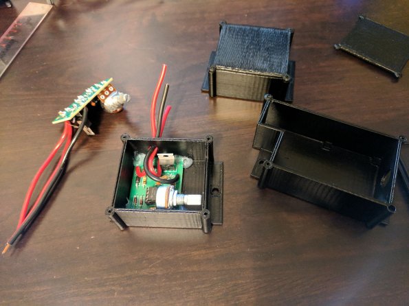
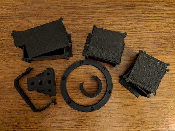
 
Last edited:

vpogv

Active member
I think I am beginning to understand your approach. The same LED can be dim or bright depending upon whether it is tasked as a running light or a brake light. You lower the current for the dim mode. This means that there are two ways to light the same LED. Two different current paths that must be kept separate.

Correct. These are terrible drawings but this is how I used them in my situation. The issue is that one LED array (side marker) was for parking and blinker while the parking and blinker for the other two arrays (taillights) were split between two arrays. Hopefully these are self explanatory but if not let me know or PM me.

IMG_20170919_161319~2_595.jpg


AFAIK, since LEDs are digital, they have only two states: On or Off. There is no true analog dimming that can be made with a resistor or by fluctuating current or voltage. "Dimming" on LEDs is done thru Pulse Width Modulation (PWM), which is basically turning the LED on/off REALLY fast. .....

Times haven't changed and this is exactly what I used. Put together 4 of these kits to run my parking lights. Another one will probably run the dimming of the dash lights just because I bought 6 of them total. :) Modeled up and printed enclosures for them as 2 are going to be in the engine bay. FIgured they should be protected at least.

IMG_20170909_233807_595.jpg
 

vpogv

Active member
I'll throw a topic up in another subforum here for future searching but does anybody have the wiring diagrams for the standard Stewart Warner gauges? Specifically Tach, Oil and Fuel.
 

B57-1974

Member
AFAIK, since LEDs are digital, they have only two states: On or Off.

Well, actually, they are not digital. They are current controlled devices. This means that they can be dimmed by lowering the current. It is true that you can't simply lower the current by putting in a bigger resistor. I have LEDs in my chandelier that can be dimmed. I guess I should have continued reading your post. Yes, you can also control brightness using PWM.

I have actually done more reading at this point. Some LED dimming systems will use current control to dim to a certain level and then at the very dimmest levels will switch to PWM to dim the LED further. Current control at very dim levels can be inconsistent due to the fact that a current sense resistor is used and at very low currents, the sense voltage is susceptible to noise. This causes flicker at very low light levels.
 
Last edited:

vpogv

Active member
Decided to start getting wiring done for the dash section as it was taking up space in the garage and hindering the wife's car from parking inside. First was to finish up the warning and indicator lights. I printed up a back that could hold the LEDs nicely. It's not pretty but it works.

IMG_20170927_222500_595.jpg


IMG_20170927_222432_595.jpg


I ended up using some heat shrink and silicone to organize the wires and add support to the seemingly fragile ribbon wire.

Got the gauges wired up and wires organized into a nice 12pin molex that my dad had laying around. :) The only issue is that the smaller 2 gauges aren't getting a good ground for the gauge lights. The gauge itself works when tested so I know it's getting ground just not to the light.

IMG_20171015_212223_595.jpg


The last bit was done to add dash lighting to light up the "hvac" controls. I will grab better pictures of how the LEDs are done but with some help of another 3d printed piece to control the light around the fan control it turned out well. Cleaned up the wiring and added a junk yard connector for simplicity.

7796d1473452635-pogs-sterling-ccc293-dask_panel1.jpg


IMG_20171015_212235_595.jpg


All wiring was secured initially with some hot glue and then revisited with silicone. I may go back with a 2 part epoxy to adhere the printed pieces. As I don't want to pull things apart after a year or so when the glue decides to let go.
 
Last edited:

vpogv

Active member
Well after a week of reflecting I decided to tear out ALL of my printing pieces and reprint in ABS. I know the PLA simply will not work and will warm quickly with any sort of heat. Sadly I 3 of my LEDs didn't make it when tearing apart but that's a small price to pay to ensure the pieces will last in the heat.

Personal printer will be here tomorrow and hopefully begin printing next week after a few tests.
 

vpogv

Active member
Well I must say this is the best $250 I have spent in a long time. Print bed is small but perfect for what I need. Plus the quality prints is better than what the other printer I had access to was doing.

IMG_20171030_231256_01_595.jpg


IMG_20171031_200445_595.jpg


Everything reprinted in ABS and even got the PWM circuits swapped to the new housings tonight. Hopefully get them wired back in later this week.
 

vpogv

Active member
Can't let Brett have all the updates - so here goes. Things have been sidetracked due to house items (yay for insulating a crawlspace!) I had some time the last week to do a little though.

First off I got all of the reprinted parts reinstalled in the gauge cluster and the center console controls. I am not happy with how I originally mounted the PWMs for the taillights so I need to rethink those.

IMG_20180121_221055_595.jpg


This is the relay enclosure for the canopy switches which I tested and surprisingly it works as I hoped. *thumbs up* The switch on the side of the box is a backup canopy switch on the outside chance the wireless entry dies. I will clean up the wiring on this guy and move on to the next thing.
 

Peter

Active member
If only I could A, afford it and B have a clue how to program it I would love a 3D printer, there is a list of stuff ranging from Opel Astra digi-dash bulb holders (no longer made) to enclosures I could make.
(Not to mention a full size BB8 droid)
 

vpogv

Active member
If only I could A, afford it and B have a clue how to program it I would love a 3D printer, there is a list of stuff ranging from Opel Astra digi-dash bulb holders (no longer made) to enclosures I could make.
(Not to mention a full size BB8 droid)

Oh you never know how much you can print until you have one. They are not ugly expensive but not cheap.
 

Nic

Active member
Additionally, there is no programming to do. You design a part, save/export it and send it to the slicer, which is what communicates with the printer. Depending on the size/complexity... wham-bam, bobs yer uncle and you have a part.

Side note: Pog, I just bought a 5 pack of stainless steel extruder gears from Amazon, my brass gear was missing some chunks out of it so it wasn't pushing the filament into the hot end and just grinding the filament. I'll get it installed tonight, then do a print for my cousin who asked for something last week. Check your extruder gear for signs of wear.
 

vpogv

Active member
Lots of nothing going on. Trying to get the motivation to finish wiring but has been tough as the wiring I have to do now is what I did before and just have to redo and document. *very frustrated*

I spent 30 min tonight plumbing up the gas filler tube. Ended up being a fairly simply run once I had some pieces to mess around with. I did have to trim a little more away from the body than I wanted but I'm not worried plus there is no chance of the body rubbing on the tubing.

IMG_20180402_210232_595.jpg


IMG_20180402_205451_595.jpg


IMG_20180402_205502_595.jpg


Some nice t-bolt clamps and I am pleased! *thumbs up*

Hopfully I'll get into the groove again soon.
 

vpogv

Active member
Wiring is almost complete and I am going to turn my attention to getting the engine ready to get put in. I am currently planning on plugs, wires, rotor, cap, belt(s) and fresh oil. To save myself frustration I was going to buy a new carb.

Is there anything else I should do while the engine is out. I do not intend to tear it down at this point so beyond that any advice is welcome.
 
Top